Intersection creates only the geometry where the two inputs overlap and combines attributes from both sides.
Intersection keeps only the geometry shared by two layers
Processing → Intersection performs a two-layer topological overlay. It creates output where the first input and polygon overlay overlap, and combines attributes from both inputs.
This makes Intersection different from a simple visual overlap or selection. It actually constructs derived geometry for the common area or portion.
Creates overlapping geometry and combines attributes from both inputs.
Uses a polygon mask to trim the first input but does not copy mask attributes.
For polygon layers, keeps the complete topological coverage from both sides rather than only their overlap.
Choose both inputs and their scopes
Select the first input layer and the polygon overlay layer. Each can use an explicit Processing scope such as All, Filtered or Selected. This matters when the project contains a statewide layer but only one district, category or current selection should participate.
For a repeatable subset, prefer a filter over a temporary manual selection. For a one-off spatial subset, a selection can be appropriate.
Confirm the geometry relationship is the one you intend
The first input can be point, line or polygon geometry; the overlay side is polygon geometry. The output keeps the first input's geometry family where possible, trimmed to the overlap. For polygon-on-polygon work, that produces polygonal overlap areas.
If you only need to know which records intersect, use Select by location rather than creating new geometry.
Check alignment before running the overlay
Intersection depends on both layers describing the same real-world locations. A wrong source CRS or coordinate interpretation can create a plausible-looking but empty or displaced result. Review the source layers in the CRS workspace if alignment is uncertain.
Invalid polygon topology can also cause robust overlay to fail or produce unwanted fragments. Use Geometry Health on suspect inputs before an important overlay.
Preview the overlap on the map
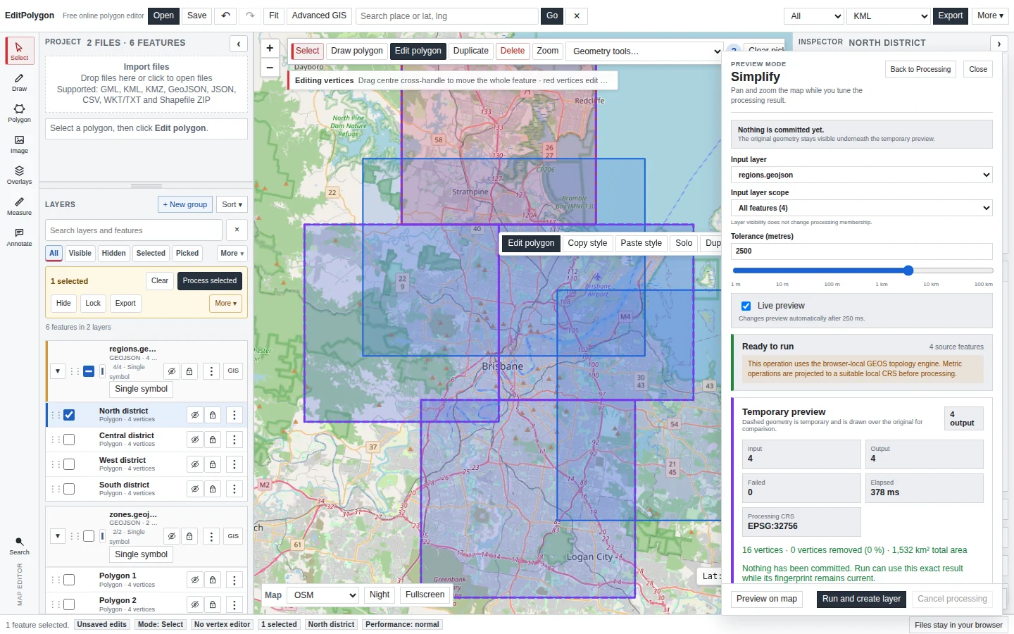
Choose Preview on map and inspect the shared geometry before committing. Look for slivers along nearly matching boundaries, unexpected gaps, multipart output and whether the scoped features are actually the intended pair of datasets.
Expect fields from both inputs
Intersection uses a combined schema policy. Output features carry attributes from both sides of the overlay, with collision-safe field handling where source names overlap. This is one of the main reasons to choose Intersection instead of Clip.
If the goal is to attach attributes based on a spatial relationship without cutting geometry, use Join attributes by location instead.
Run, validate and export
After the preview is satisfactory, choose Run and create layer. The result becomes a derived project layer with Processing provenance while both inputs remain available for comparison.
Validate complex polygon output when it will be used for further overlay, area-sensitive decisions or authoritative export. Then use the correct export scope described in Export data and save projects.
Common Intersection questions
What is the difference between Clip and Intersection?
Both can keep overlapping geometry. Clip preserves only the first input's attributes; Intersection combines attributes from both inputs.
What is the difference between Intersection and Union?
Intersection keeps only the common overlap. Polygon Union keeps the complete topological coverage from both inputs, including areas that belong to only one side.
Can I intersect points with polygons?
The current tool allows the first input to be point, line or polygon geometry and uses a polygon overlay. The result follows the first input family where possible.
Why do I get small sliver polygons?
Slivers usually reflect the real source boundaries: tiny gaps, overlaps or nearly coincident edges. Inspect source topology rather than automatically deleting them.
- Both input layers and scopes answer the intended spatial question.
- The overlay side contains compatible polygon geometry.
- CRS interpretation and geometry validity were checked where uncertain.
- The preview shows the expected common geometry.
- Combined attributes are actually required; otherwise Clip or spatial selection may be simpler.
- Complex output was reviewed before export or downstream analysis.